Scaling up
1D → 3D
This is when the project (and the problems) started to get much more complicated and less organized. Instead of small walls I could break through after some research, the last few walls were much taller and involved a lot more experimental tinkering, with me only understanding why the fixes worked in retrospect. At this stage there were also fewer "solutions" and more "workarounds," as proper solutions would likely have required large amounts of other changes and rewrites. My general debugging workflow was software → my wiring/hardware → the boards themselves. If that didn't fix it: isolate the problem, do more research, and repeat.
3D physics sim software
Suddenly there was an issue I hadn't dealt with in the 1D sim: simulated pixels I couldn't see. The sim only displays on the surface of the cube, so the internal state was effectively invisible. If I did this again, I would write a Python script to render what was happening internally, but at the time I just ran the sim slowly, output all the pixel data, and stored a lot about the process in my head (and on paper).
The data writing takes time
I found that my friction-fit jumper wires were no longer consistent enough. When you're writing 64 pixels every 30 ms, a small gap from a loose wire isn't likely to break the output; when you're writing 384, signal integrity starts to matter (384 LEDs take 11.4 ms to write, about a third of the delay time). A small break in the stream causes the LEDs to read a reset. They then start reading garbage once the break resolves and the data joins back mid-write. This didn't happen much at 64 pixels, but when you're spending half of each cycle writing to the panels, it becomes much more of an issue. I made the decision to move to perfboard here, but I didn't love it: my electrical problem was solved, but it didn't work much better than just soldering everything together with wires, and it was kicking the space/mechanical problem down the road. (Also, I wasn't able to reasonably remove the dev board once I wanted to change it, so I had to get another.)
Packing everything into the cube
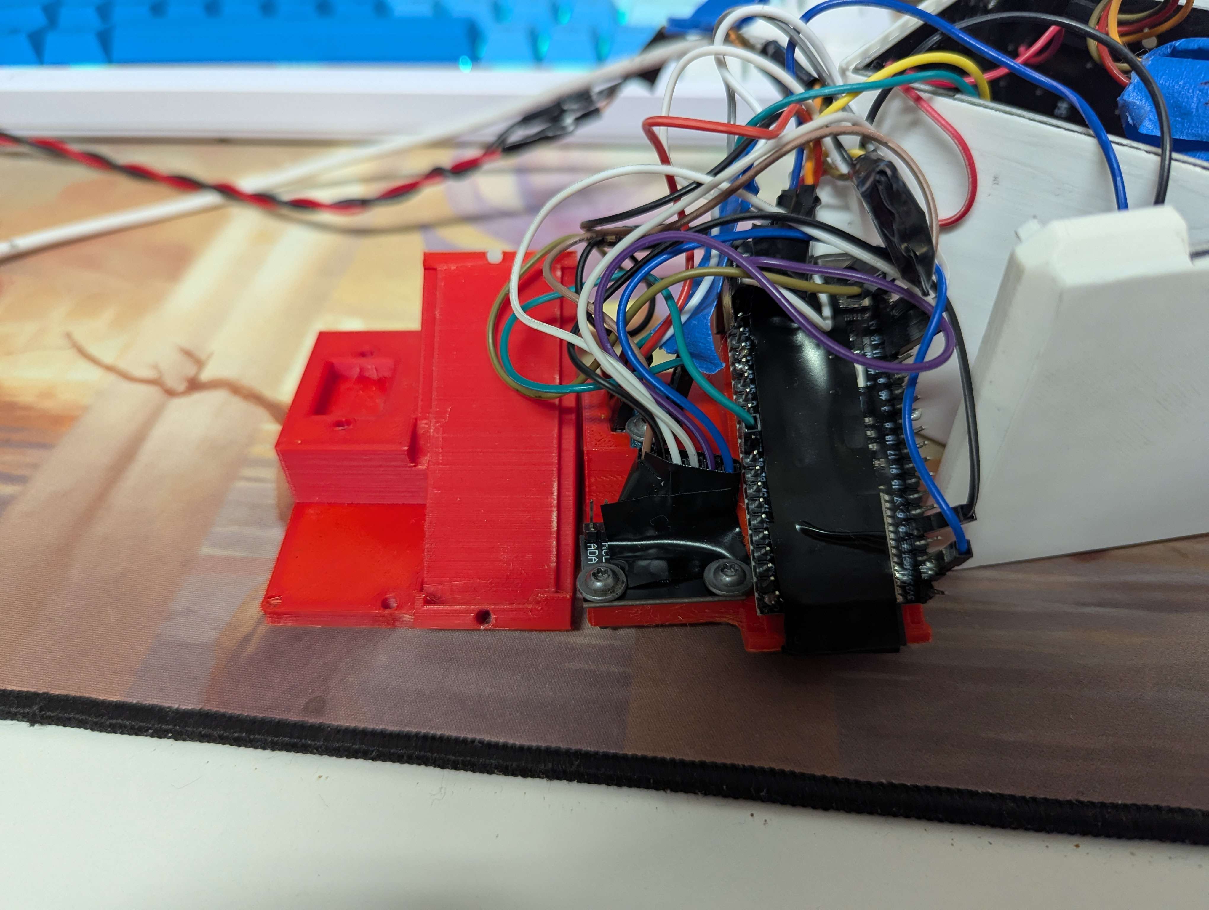
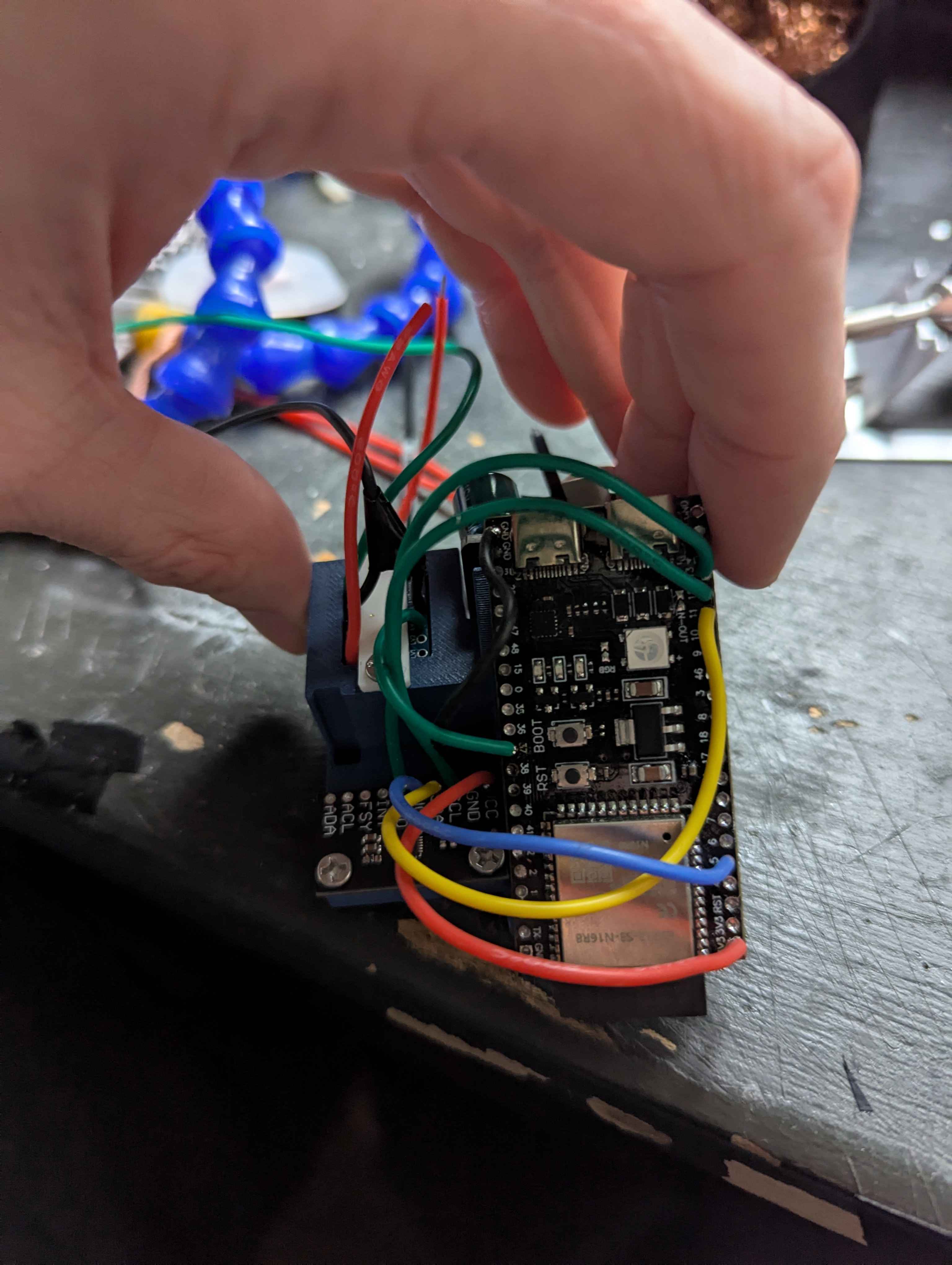
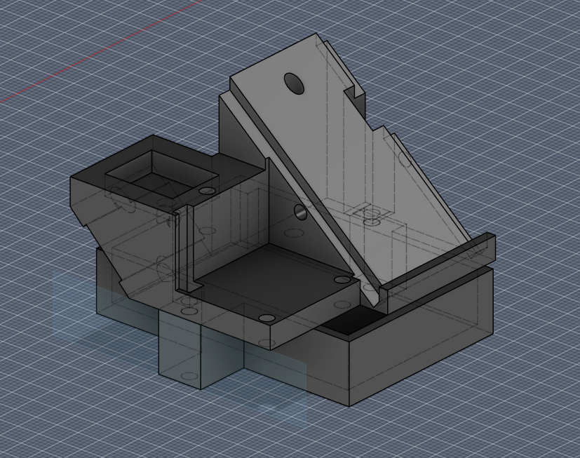
The most mechanical issue: volume limitations. The largest problem was that the ESP32-S3 dev board I was using is physically wider than the volume inside the cube, but fits at an angle (the ESP32 is 65 mm long, the cube internals only about 60 mm on a side, before the wiring takes up space). This is where I actually decided to model properly, making a mount that everything (dev board, IMU, level shifter) could attach to, and that just barely managed to fit inside the volume of the cube with all of the wiring.
It took many iterations, a lot of which were dealing with inconsistencies on aftermarket boards (my LED panels were not square, and the four screw holes were each 1–2 mm off from centered). I initially soldered male jumpers before realizing I could just buy low-gauge wire and cut it to length. In a future project, this is where I would reach for a custom PCB that I could make fit perfectly, with screw holes to mount with. At the time, I didn't feel comfortable at that level, which is what led to my custom dev board project as a way to break into PCB design.
It worked on my bench supply, not on portable power
The big bad no-good brownout problem. I wanted to take this project to OpenSauce 2025, which meant it had to be portable. I had a DIY benchtop power supply that I'd been using to power the project up to this point, and it was working well. The idea was to use a portable phone charger, but when I wired it up, the project would work for 1–2 seconds before the IMU stopped giving data. I initially suspected electrical noise was causing the sensor failure; I learned about decoupling capacitors and wired some up to both the supply and the sensor, but found they didn't help. I then suspected my software. I was running the sensor over I2C at the time, as it was what I was familiar with, but I had learned SPI was more error-tolerant, so I rewrote my sensor library. This didn't solve the problem either. I kept the SPI version though; the second pass was a lot cleaner and gave me an excuse to implement features like burst read/write.
Eventually, after a lot of trial and error, I isolated the issue to the combination
of the cheap linear regulator on my ESP32 dev board and the high source impedance of
the portable charger. The LEDs would draw amps of current, the charger's output
would sag, and the 3.3 V regulator (an AMS1117) would sag below the
cutoff voltage of the IMU. Since I couldn't remove the regulator without a hot-air
station and precise rework, the solution I landed on was to power the LEDs and the
ESP32 from separate ports on the charger with a shared ground. This, after months of
tinkering, finally made the project portable.
My biggest takeaway from this issue in particular is the value of proper debugging tools. In this case specifically, an oscilloscope would have made this significantly easier and removed a lot of the guesswork: I could have just probed the line, seen the sag, and diagnosed it. It's part of why I'm particularly excited for university, where I'll have access to a lot of the tools that are outside the scope of my home workbench at the moment.
The battery — perfect is the enemy of done
Bringing this project to OpenSauce led to some very interesting conversations, and they gave me a lot of confidence in the project. One in particular stuck with me: I was talking with some of the BattleBots people, and after looking at the internals of the cube they said something along the lines of:
You could probably cut some wires shorter and shove a LiPo in there.
The reason I had been so hesitant to introduce battery power was that I wanted to do it "correctly": measure current draw, spec a BMS to it, and find a breakout. I decided to just do it the easy way for this one, as I wanted the project finished. I got a battery with a good amount of capacity and a BMS with overcharge protection rated for 1 amp, and capped the LEDs at 1/25th of their max brightness to stay under that current:
So this project has a LiPo in it. I understand what I would do to implement it correctly, but this isn't exactly that. If this were a product or a gift, I would take more precautions, but for something that sits on my desk and occasionally gets brought places, this is as far as I took it.
The combination of the brightness cap and the battery's low source impedance also solved the brownout problem, so I was able to recombine the voltage lines and resolve a past problem in a different way.